High Current Linear Regulated Bench Power Supply

On this page, some aspects of the construction of a linear regulated bench power supply using the 2SC2922 power transistors are discussed.
All started with a high power transformer rated with 26,5V AC and 8.5A current which I could get hands on for 5€ at a trade fair, some industry spare stock high capacity capacitors for a bargain and a heavy duty metal case from a 230V/115V transformer which I got for free. Since I only owned a commercial 30V/2.5A adjustable power supply up to then, the wish for the possibility to provide higher currents was imminent.
There are many schematic available on the internet, but as soon as you exceed 3A current, there
are not so many examples left. It becomes even worse when you require an adjustable current limiter down
to zero and maybe also voltage regulation down to zero. The main issue is the lack of information whether
the stated power/current can be drawn continuously and if the design is really
short-circuit-proof (without using fold-back-current limiting).
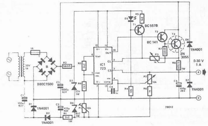
My first attempt was the LM723 variant of the
variable 0..30V regulated power supply for 20A max.
published on www.pocketmagic.net (which is a page worth looking at for random high current/high voltage projects).
Since it uses the LM712 chip it is a temptingly simple design but voltage can only be adjusted down to +2V
and the maximum operating voltage is 37V which is below the peak rectified idle voltage of my transformer
(note that all parts between the transformator and the regulating transistors must be sized for the peak
idle voltage of your transformer
(which is approx. 1.10 x √2 x the rated voltage (1.10 is a conservative guess as transformator factor
for high power transistors but can be higher for transformators with less iron inside (mine was 1.06 for example -
just measure the idle voltage and multyply by √2 for the peak current)))).
Despite those drawbacks, I built the PCB but there were several (for me) not solvable issues:

Current Tracking Power Supply for Sensor Calibration, Joshua Brookley, California Polytechnic State University
2. The current limitier on the initial design sets in at 4.4A on its lowest setting as 0.65V drop on the 0.15R current sense resistors. Increasing the resisitor would easily reduce this limit to any desired value but the output impedance of the power supply would be increase by this to unacceptable values (so reducing the maximum output voltage of the power supply under high currents). I tried to trigger the 0.65V on Pin 2 with comparators (LM393) and especially with the LT1789-1 instrumentation amplifier (basically working with separate low-side current sensing) but all functional attemps ended in heavy oscillations due to the (slow) input amplifiers and the (fast) LM723 current limiter. Following this thread I tried several variants to boost Pin 2 voltage by the voltage drop over a constant current source as described in this schematic. It basically worked but since no solution for the shortcoming of 1) was at hand, I skipped this design. There was simply no use for a regulated high power supply which would not regulate adequately under high power. It might be suitable to power regular devices but for an accurate laboratory bench power supply the need for a perfect voltage regulation and reliable current limitation is out of question.
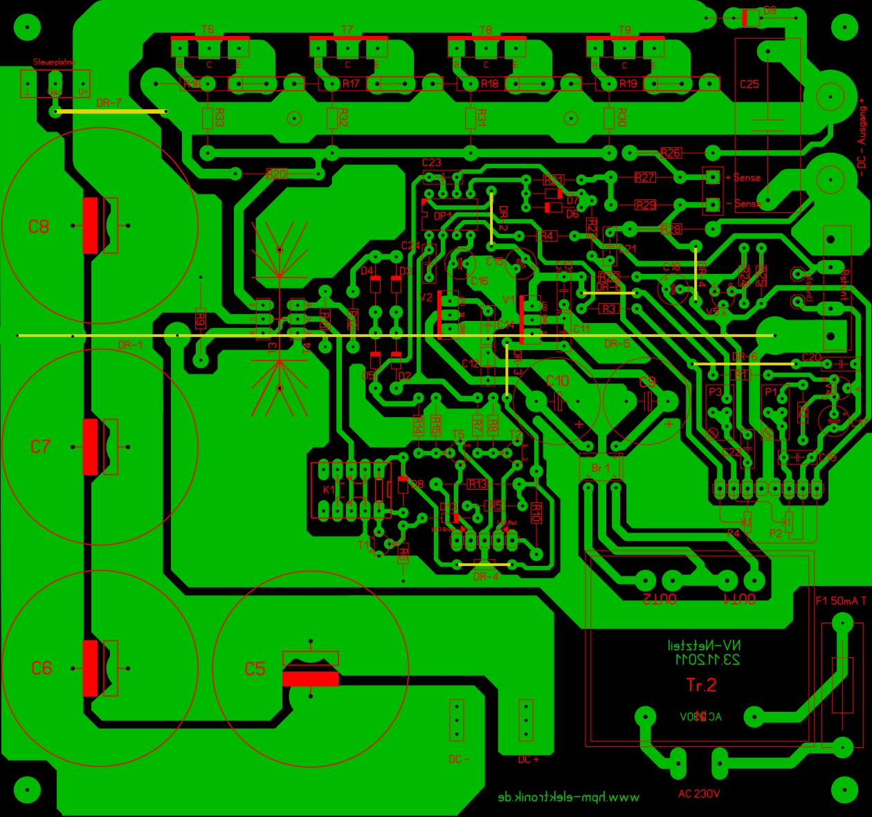
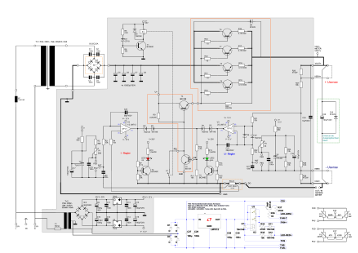
After this excursion I spent some time searching for a more suitable design. On a co-workers advice I was looking for a modular design with independent voltage and current regulation circuits. Next to some commercial designs of the analogue age (which are mostly to complex to build at home) I found a very promising design (PCB to the left) which my variant is based on: the NT 30V-15A power supply of H. Mauz which he has thankworthily published on www.hpm-elektronik.de It was developed for 30V and 15A continuous current and has three separate PCBs for the regulator, thermal management and control and a TRIAC-pre-regulator. All in all this has turned out to be a very mature design and my simplified version of it worked as it should right after assembly. Many thanks to the tidious investment of time and effort in this power supply and the kindness to make it publically available in the internet.

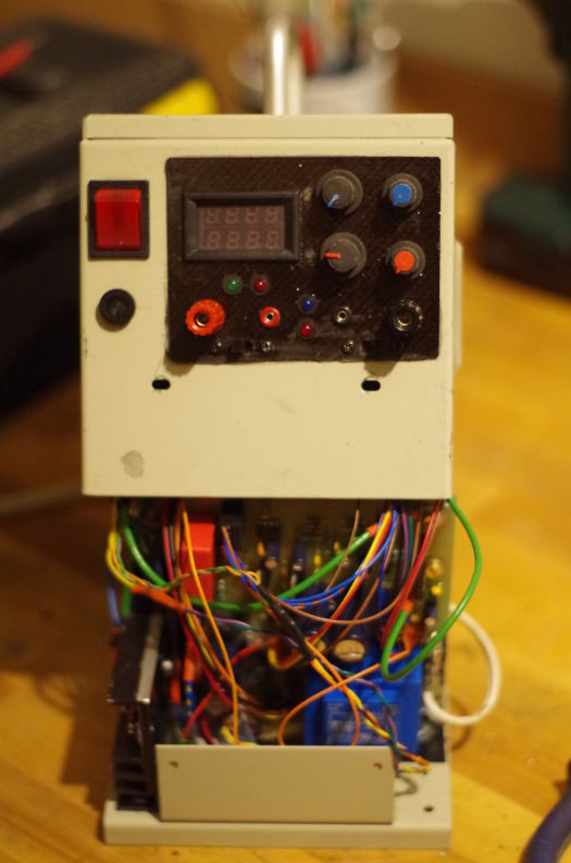
The built power supply (PCB to the right) is a reduced variant which uses only one 115x125mm PCB for the power supply including a simple thermal control (using an opening bimetal switch on the heat sink to activate fan cooling (connected to the THS pins)). The rectifying capacitors are removed from the PCB (I mounted them to the case for sturdiness). Also the base and emitter resistors were moved from the PCB to the transistors on the heat sink. The schematics below are adjusted for my special case of 26.4V/10A output and it does not have any pre-regulators any more. To be able to drive the fan directly from the onboard low-power transformer, I selected the next bigger transformer from this series. There are two new LEDs on the front panel. The green light is on when the thermal control is powered (running) but the heat-sink is cooler than the bimetal switching temperature. The red light signals the overheat-condition where the fan is turned on until the cut-off temperature of the switch is reached. Until then, the green LED is flashing with the tachometer signal (FAN-T pin) of the 3-pin-CPU-fan so you are warned when something is blocking the fan or it is not running as intended.
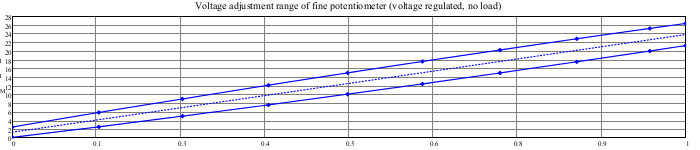
Measurement of voltage fine adjustment range:
Measurement of current fine adjustment range:
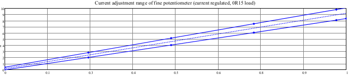
I also made some basic static measurements for the voltage/current continuity under load and thermal stability. These data series have been recorded using Unitrend UT-61d multimeters with a data rate of approx. two Hertz so this is more or less a rough long-term measurement than an oscilloscope analysis and true dynamic effects could not be documented. Anyway it was sufficient to evaluate the quasi-static regulation quality and the resulting charts can be found below for your information. The blue line is the voltage in Volts, the red line the current in Amperes.
For an optimised measurement of the regulation characteristics under load, a constant resistance dummy load is required. True constant resistors for powers of up to 300W are expensive and hard to find. As an affordable alternative which does not dwindle into an own project, I used 4 halogen light bulbs for 12V/50W which I connected and deconnected in different variations. See here [High power resistive dummy loads] for more details.
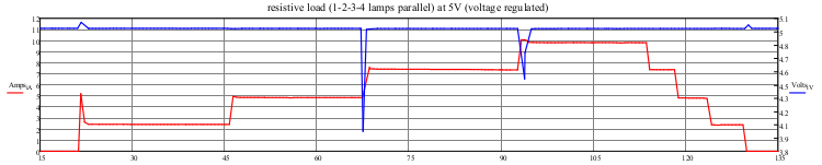
At the moment of connecting the bulb glowing filament is cold and has very low resistance but heats up in fractions of a second to its rated power/resistance. I connected the bulbs manually with temporay alligator clamp laboratory wires so arcing could not be prevented, especially at disconnecting, which should be kept in mind when observing the voltage peaks at the current steps below.
Voltage regulation at 5V with 1,2,3,4 lamps in parallel:
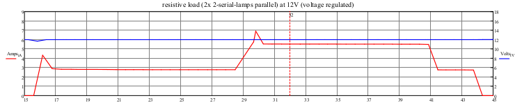
Voltage regulation at 12V with 2 lamps in serial and 4 lamps 2-serial-2-parallel:
Voltage regulation at 26V with 2 lamps in serial and 4 lamps 2-serial-2-parallel:
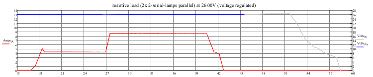
All in all, the influence on the voltage was less than 3mV at a time 1.5s after connection of the load change, which is a very satisfiable voltage continuity.
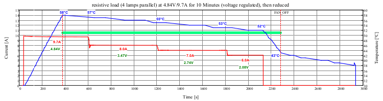
Temperatur control and thermal stability:
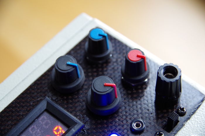
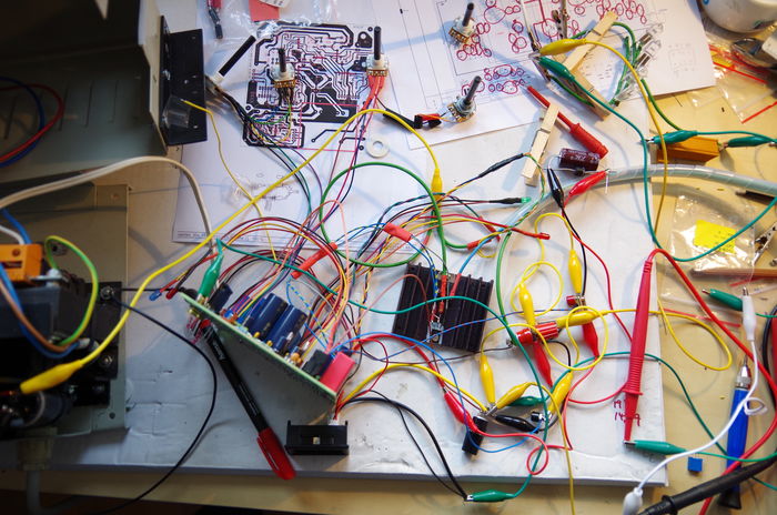
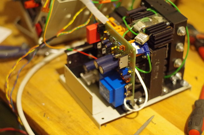
Pictures


Hopefully helpful advice
Some brief advise for those who plan to build a power supply on their own:Use a big casing. Although anything worked fine for me (except maybe thermal convection) with my tiny case, I don't like the fact that I do not exactly know where the cables run when I finally managed to close the case with no cables sticking out. A small case has its advantages regarding handyness, but it gets heavy anyway from the other parts like the transformer and heat sink you will need, so it seems to be better to have enough space for a professionell, doubtless cable routing.
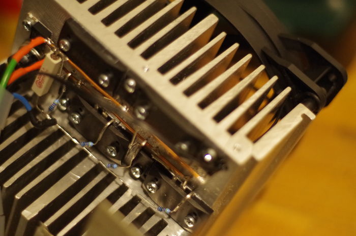
Use a big heat sink for active (fan) cooling. Since forced convection increases the power dissipation you can get big temperature gradients so be sure to have a good and not too long heat-conducting path from the transistors to the fan side.
Use a nicely oversized transformer. Since there are power losses everywhere and the power rating of transformers was most likely determined under free convection (and not stoved into a closed case) and maybe for duty-cycles less than 100%, you will need some heavy reserve for continuous power consumption.
Don't use cheap chinese digital voltmeters. The one I used was available for 10€ (including shipping from china). It does its job - partwise. There is one input for voltage and one input for current, but only one common ground. So, depending on how you connect it, you either have the voltage drop of the shunt included (which is up to 200mv although it was rated for 10A) in the displayed voltage, or the current somehow magically divides between the voltage and current sense wires which gives you unrealistic low displayed currents. This is not exactly high precision. Better use separate displays or better combined displays.
Downloads
Schematic [Board Version 1.1]
Parts list (not complete, use with caution) [OpenDocument-Spreadsheet] [PDF]
Board files [Sprint v6.0, Board Version 1.1] [Gerber, Board Version 1.1] [JPG, Board Version 1.1]
Helpful links
[Current sensing tutorial using OP-Amps]
[Trifolium power supply design manual]
[ PocketMagic: Variable 0..30V regulated power supply for 20A max.]
[Original Power supply by H. Mauz]
[ Back...]