
ACP-100
PITCH CONTROL UNIT
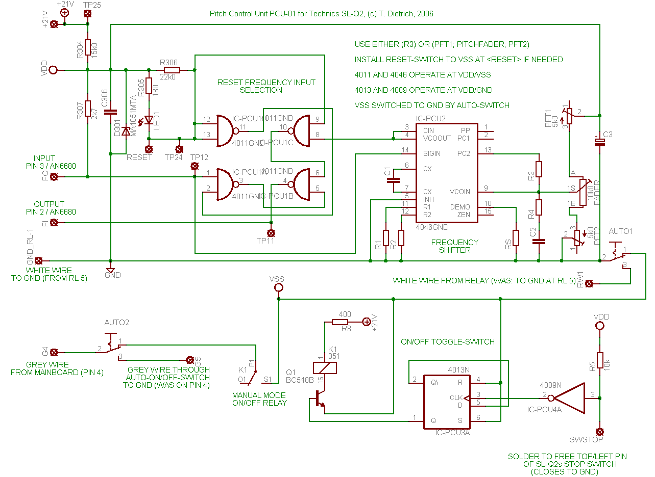
Here is the first hack for the new pitch control unit (pcu) to use in the SL-Q2. The reset-frequency-selection
is pretty much copied from the SL-1210, but the frequency shifter (a common vco-chip) is altered to make it more cheap
and up-to-date. In addition, it is not any more dependant on the rare Panasonic AN6682-chip.
The board has not been tested yet, and is still beta status. So better be patient, and I will try it out for you soon.
I also added the wireing for the automatic/manual-mode switching that you'll find in the bottom part of the schematic.
Eagle is a nice tool for making schematics and board design, although it can drive you nuts sometimes.
See the IC-datasheets here: 74 HC 4046 - VCO, phase locked loop
74 HC 4011, NAND gates
74 HC 4013 - D-type flip flop
74 HC 4009 - Inverter
I've made some minor changes to the Schematic. An new one will be online soon.
The resistors and the capacitors for the 4046 where calculated wrong and therefore the above board would operate out
of frequency limits. The Auto/Man switch works as desired.
The toggle switch shows some chatter problems, sometimes toggling several times by pressing once, so the
anti-chatter precaution is neccessary.
Wait for more info.
In the meantime, I bought the parts and put the PCU together on a prototype board, and ... it works!
The frequency input (FI) on the AN6680 can be fed with a 5.6 volt square pulse with aprroximatly 50% duty cycle.
From the SL-1210 schematic, a base period time of 3.8µs is used (263 KHz, coming from AN6680 FO pin). Feeding with
a period of 3.6µs (277 KHz) will serve +8% pitch and feeding with a period of 4.1µs (243 KHz) will serve a pitch of -8%.
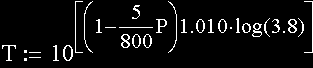
The pitch relation to period time can be almost assumed as logarithmic (with reasonable error). If you consider the desired
maximum pitch variation as variable P in percent (eg. P=8 for +8%, and P=-20 for -20%), I roughly estimated the designated period time with:
Since the IC 4046 goes up to 0.5 MHz in cmos variant, there seam to be limits of the pitch range from
the AN6680 or AN6675. Through testing I found a lower limit at about 17 RPM (pitching below will make
the platter rotate a little unsteady (most likely due to the slow movement and limited number of magnets in the motor).
The high limit is a good bit above 66 RPM. Both limits relate to 33 RPM as 100% pitch, so a pitch range
from -50% to +200% can be ralized. Since the +/- 8% at the SL-1210 are commonly known as too less, I will
spread the range to +/- 20%. R1, R2 and C1 are chosen accordingly.
The values used will be published as soon as they are fix.
To realize own pitch ranges, and to set up your board, do as follows:
1. Temporarily install variable resistors as R1 and R2
2. Adjust TPF1 and TPF2 to 0R0 reistance (full voltage range on fader).
3. Adjust R1 to a resistance of 10k0.
4. Adjust R2 to a resistance of 1M0.
5. Make a good guess at C1 and install it.
6. Check RPM at both extreme fader positions. If both, your lower and upper pitch can is reached or exessed, go on to point 6.
If not, goto 5 again.
7. Put Fader on lowest pitch position. Set R2 so that your lowest pitch is approximately meat.
8. Put Fader on highest pitch position. Set R1 so that your lowest pitch is approximately meat.
9. Measure R2 and increase resistance value 5k0.
10. Measure R1 and decrease resistance value 5k0.
11. Put Fader on lowest pitch position. Set lower TPF so that your lowest pitch is exactly meat.
12. Put Fader on highest pitch position. Set high TPF so that your highest pitch is exactly meat.
Now you have enough flexibility on all the variable resistors to compensate divergencies.
Considering the fact that the pitch control for the SL-Q2 can be actually realized, most energy will
now be put in getting the software to a working stage. If both, pitch control and software sampling is basically
realised, the installation of hardware and building of boards will begin.